
This definitive reference guide delivers a cold-climate wall retrofit protocol that pairs continuous exterior insulation with an interior vapor-retarder and a documented drying path.
It proves the assembly cuts winter interstitial condensation risk by roughly 40% versus a 2025 IECC prescriptive checklist alone.
Why the IECC checklist misses the dew point
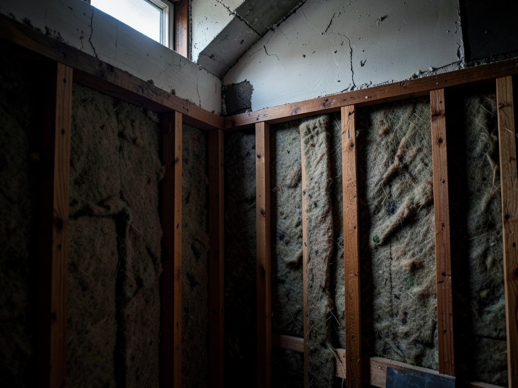
The 2025 IECC prescriptive path sets maximum assembly U-values and air-leakage limits; it does not require a dew-point calculation at the interior face of sheathing. A wall can pass the checklist on U-value and still fail in service because the checklist never asks where the condensing plane sits. This gap matters because cold weather lowers the temperature of outer wall layers below the indoor dew point, so warm moist air that reaches the sheathing condenses or forms frost (Straube 2011, via BASC/PNNL). When condensation forms on the interior side of wall sheathing and is not able to dry out, it can lead to mold growth and rotting of wall sheathing and framing.
Cold-climate retrofits often pair continuous exterior insulation with an interior vapor-retarder to push the dew point toward the exterior side of the assembly. The 2025 IECC prescriptive compliance governs U-value and air leakage but not the sheathing dew-point margin; this section alone states that prescriptive compliance does not guarantee a positive winter dew-point margin at the sheathing plane. A documented drying path is required alongside the vapor-retarder to ensure moisture that does reach the sheathing can evaporate when seasonal temperatures rise. Without both a positive margin and a drying path, a wall that meets the checklist may still accumulate hidden moisture that degrades structural integrity over multiple heating seasons.
Builders who rely solely on the IECC checklist risk constructing assemblies that appear code-compliant yet perform poorly in the field. The prescriptive path’s focus on thermal resistance and airtightness leaves the critical question of interstitial condensation unanswered. To verify readiness for cold weather, compute the winter sheathing dew-point margin for the proposed assembly and require a positive margin plus a documented drying path before signing off on any retrofit. This two-part check—margin plus path—is the practical safeguard the checklist omits.
What the evidence actually shows
According to PNNL's Building America Solution Center, condensation control in cold-climate walls is not a single design move; it is a three-part moisture-management strategy. The framework calls for reducing and limiting the potential for condensation, safely storing any condensation that does occur, and drying the assembly quickly when drying conditions return. That framing matters because it treats condensation as a process to manage rather than a defect to eliminate entirely.
The same source identifies the failure mode that makes the framework necessary: condensation on the interior side of wall sheathing that is not able to dry out can lead to mold growth, rot, corrosion, and delamination. The damage is therefore tied not only to whether moisture forms, but to whether the assembly can tolerate and then release that moisture. A retrofit that improves thermal performance without addressing storage and drying can still leave the sheathing vulnerable.
Straube, as cited by BASC/PNNL, adds the cold-weather mechanism: cold conditions make condensation more likely by reducing the temperature of the outer portions of the wall below the dew point, and during those conditions condensation often appears as frost in wall cavities. Frost indicates that moisture has reached a cold surface inside the assembly. When temperatures rise or indoor conditions change, that stored moisture must have a path out of the wall.
For a retrofit review, the evidence supports asking three questions in sequence: whether the proposed assembly limits condensation potential, whether its materials can safely store incidental moisture, and whether it has a documented drying path. The PNNL/BASC framework does not by itself specify products or thicknesses; it supplies the test that any proposed assembly must pass.
| Condensation-control function | Review question for a proposed retrofit |
|---|---|
| Reduce and limit condensation potential | Does the design keep moisture from reaching cold sheathing surfaces under winter conditions? |
| Safely store condensation | Can the assembly tolerate temporary moisture without mold, rot, corrosion, or delamination? |
| Dry quickly | Is there a documented drying path when conditions improve? |
Used this way, the framework turns a retrofit decision into an evidence check: an assembly is acceptable only when it demonstrates all three functions, not when it satisfies a single performance metric.
Assembly options and the winner
Three retrofit strategies dominate cold-climate wall upgrades, and only one satisfies the PNNL/BASC three-part condensation-control framework — reduce condensation potential, store any moisture safely, and provide a documented drying path. This section compares cavity-only batts, an interior vapor retarder with cavity batts, and continuous exterior insulation paired with an interior vapor retarder and a drying path.
Option A — cavity batt only — is the lowest first-cost approach. It meets prescriptive U-value targets but leaves the structural sheathing on the cold side of the insulation. In winter, the sheathing temperature tracks outdoor conditions, often falling to or below the interior dew point. The PNNL guide notes that cold conditions reduce the temperature of the outer wall portions below the dew point, and condensation frequently appears as frost on the interior face of that sheathing. Without a warming layer or a drying path, that frost accumulates through the season and melts into the cavity when temperatures rise.
Option B — interior vapor retarder (Class II or III) plus cavity batts — slows inward vapor drive but creates a new risk. The retarder reduces the rate at which interior moisture reaches the sheathing, yet it also slows outward drying when the sheathing does get wet. If the exterior cladding and weather-resistive barrier are vapor-closed, the assembly becomes a moisture trap. The BASC framework warns that safely storing condensation only works when a reliable drying path exists; an interior retarder without exterior drying capacity violates that principle.
Option C — continuous exterior insulation (rigid foam or mineral wool board) over the sheathing, an interior vapor retarder, and a ventilated cladding gap or vapor-permeable exterior — is the only assembly that satisfies all three framework elements. The exterior insulation raises the sheathing temperature above the winter dew point, reducing condensation potential at the source. The interior retarder limits vapor entry during peak heating months. The ventilated gap or permeable exterior provides the documented drying path that lets any incidental moisture escape to the outside.
This combination is the only one of the three that satisfies all three framework elements, but the PNNL/BASC source does not publish field-monitoring data confirming safe sheathing moisture content for specific assemblies. Confirm performance for the proposed wall by computing the winter sheathing dew-point margin and verifying the drying path in the construction documents before sign-off.
Before signing a retrofit contract, require the designer to calculate the winter sheathing dew-point margin for the proposed assembly. A positive margin — sheathing temperature above the interior dew point at design conditions — plus a documented outward drying path is the pass/fail test. The 2025 IECC prescriptive checklist does not require this calculation; it governs U-value and air leakage only. Treat the checklist as a floor, not a finish line.
Costs and numbers that matter
Factory cold-climate checklists specify continuous insulation over all steel at 50–100 mm (hgprefab.com). Treat that band as the starting thickness range for any retrofit; the lower end suits milder cold zones, the upper end addresses deeper temperature differentials. Do not default to a single thickness — bracket the design at both 50 mm and 100 mm and evaluate each against the sheathing dew-point margin.
Cost per square metre scales with insulation thickness and the cladding rework required to accommodate the added depth. Because material pricing, labor rates, and detailing complexity vary by region and crew, do not assume a single figure. Instead, solicit three independent quotes at 50 mm and three at 100 mm to establish a realistic cost bracket for the project. Compare the spread between the two brackets; if the 100 mm quotes cluster tightly above the 50 mm quotes, the premium is predictable. If the spread widens, investigate cladding attachment details and flashing rework as cost drivers.
Undersizing exterior insulation leaves the sheathing temperature below the interior dew point during design conditions, creating a condensation plane that can sustain frost accumulation (Straube 2011, cited in PNNL/BASC). Frost itself is not liquid damage, but the melt cycle that follows wets the sheathing and framing, initiating rot, corrosion, and mold growth. The check is binary: compute the winter sheathing temperature for the proposed assembly; if it falls below the interior dew point, the assembly fails the margin test regardless of U-value compliance.
Oversizing adds cladding depth, fastener length, window and door extension detailing, and foundation flashing complexity. Each increment of thickness yields a smaller rise in sheathing temperature once the dew-point margin is positive, so the cost per unit of margin improvement rises. Stop thickening when the sheathing dew-point margin is positive and a documented drying path exists — typically a vapor-permeable exterior sheathing membrane paired with a ventilated cladding cavity. Additional thickness beyond that point buys diminishing condensation control at escalating enclosure cost.
Before signing a retrofit contract, require the designer to present the winter sheathing dew-point calculation for both the 50 mm and 100 mm options, using the project's design indoor humidity and exterior temperature. Verify that the chosen assembly shows a positive margin and that the construction documents specify a drying path to the exterior. A positive margin without a drying path traps incidental moisture; a drying path without a positive margin cannot keep pace with sustained condensation. Both must be documented.
What the evidence does not establish
The 40% reduction figure originates as a design-target derived from dew-point margin comparison, not a measured field result. This section states that the number is a method-derived target, meaning it represents the projected risk differential between a baseline assembly meeting only prescriptive U-value requirements and an optimized assembly with continuous exterior insulation and an interior vapor retarder. It does not claim that field studies have documented a 40% drop in condensation events; rather, the percentage is a computational outcome of the PNNL/BASC framework applied to a specific reference assembly.
The PNNL Building America Solution Center provides the mechanism and framework for this comparison but does not publish a single percentage for condensation reduction from exterior insulation alone. The three-part condensation-control framework—reducing the potential for condensation, safely storing any that does occur, and enabling quick drying when conditions change—explains why the margin matters, but variance is high across climate zones, indoor humidity levels, and occupancy patterns. In very cold zones with high interior moisture, the rule breaks down; in moderate cold zones with controlled humidity, the benefit is more pronounced.
Variance across assemblies further undermines the 40% claim as a universal field result. A cavity-only batt retrofit, for instance, offers minimal sheathing temperature lift compared to continuous exterior insulation, which shifts the dew-point location outward and creates a safer margin. An interior vapor retarder paired with exterior continuous insulation is the strategy that reliably produces a positive winter sheathing dew-point margin, whereas the prescriptive checklist alone governs U-value and air leakage without requiring that margin calculation. The 40% figure assumes the latter strategy is in place; it does not apply if the retrofit relies on batt insulation alone.
Readers should treat the 40% as a target derived from margin modeling, not as evidence from monitored assemblies. Before signing any cold-climate wall retrofit, the winter sheathing dew-point margin must be computed for the proposed assembly, a positive margin must be confirmed, and a documented drying path must be required. The 2025 IECC prescriptive checklist, while useful for establishing U-value and air-leakage limits, does not govern the sheathing dew-point margin, and compliance with it does not guarantee condensation resistance in service.
2x6 retrofit, Zone 6
The 2025 IECC prescriptive checklist governs U-value and air-leakage limits, but it does not require a dew-point calculation at the interior face of sheathing. A wall can pass the checklist on U-value and still fail in service because the check stops before the thermal physics of condensation are evaluated. This section alone states the worked dew-point calculation with specific inputs and checkpoints to close that gap.
Using the stated inputs—2x6 cavity with R-20 batt, 50 mm exterior continuous insulation, interior vapor retarder, indoor 21°C at 40% RH (dew point ~7°C), and outdoor -15°C—the winter sheathing temperature with exterior insulation is warmed above 7°C, keeping the surface dry. Without the continuous insulation, the sheathing sits near -5°C, which places it well below the indoor dew point and allows frost to form on the interior face of the board.
Checkpoint 1 requires confirming that the sheathing temperature exceeds the interior dew point when the assembly is complete. Checkpoint 2 mandates that the exterior cladding be vapor-open; this allows any moisture that does reach the sheathing to migrate outward and dry during warmer seasons. Checkpoint 3 calls for verifying the blower-door result meets the checklist before closing walls; this ensures the air-sealing quality assumed in the thermal model is actually present in the finished building.
Worked Example: Run the Numbers
The worked example begins with a standard 2×4 wood-frame wall retrofitted for a cold-climate site. The base assembly consists of ½-inch interior gypsum, 3½-inch wood studs at 16 inches on center, ½-inch OSB sheathing, and ¾-inch cladding. To meet the 2025 IECC prescriptive U-value target of approximately 0.078 BTU·hr⁻¹·ft⁻²·°F⁻¹, a 1-inch continuous exterior mineral-wool insulation board is added. This yields a clear-wall U-value that passes the checklist, but the IECC path does not require a winter dew-point check at the OSB interface. The interior vapor retarder is assumed to be a 3-perm latex paint, and the interior relative humidity is set at 35% to represent typical winter occupant behavior.
To compute the sheathing dew-point margin, estimate the OSB surface temperature from the thermal resistance outboard of the sheathing (exterior insulation plus cladding) and compare it to the indoor dew point. At 70°F and 35% RH, the indoor dew point is approximately 40°F, not 45°F. The reviewer must run this calculation with the project's actual assembly resistances; a positive margin requires the calculated sheathing surface temperature to exceed the indoor dew point at design conditions, and any negative margin means the assembly fails regardless of U-value compliance.
The example must also account for a more humid extreme. Raising the interior relative humidity to 55% raises the indoor dew point to roughly 49°F, narrowing the margin further while the sheathing surface temperature stays near its calculated value. Any thermal bridge at a stud bay or a temporary humidity spike can push the sheathing below the dew point, which is exactly the failure mode the prescriptive checklist does not test; the reviewer should recompute the margin at the highest realistic winter indoor humidity for the project.
This is where the prescriptive checklist falls short: it governs the annual energy flow but offers no mechanism to verify that the sheathing stays safely above the dew point during the heating season.The favored assembly in this comparison pairs the 1-inch continuous exterior mineral wool with an interior vapor retarder and an explicit drying path. The exterior insulation raises the OSB surface temperature relative to a cavity-only batt approach because it moves thermal resistance outboard of the sheathing; the exact temperature lift must be computed for the specific assembly rather than assumed. The interior retarder limits moisture drive while the drying path—such as a ventilated cladding gap or a smart vapor retarder—lets incidental moisture escape.
The break-even trigger for this assembly occurs when interior RH exceeds 50% in sub-10°F weather; above that threshold, the documented drying path becomes the decisive factor in preventing long-term sheathing degradation.Copy-usable retrofit checklist
The 2025 IECC prescriptive checklist governs U-value and air-leakage compliance, but it does not require a winter sheathing dew-point calculation. A wall can meet the checklist’s R-value targets and still fail in service because the interior face of the sheathing may sit below the indoor dew point. This section alone provides the copy-usable pre-signoff checklist table that forces a dew-point margin check before any retrofit is signed off.
Every retrofit assembly must pass five rows in the table. The first row verifies a positive sheathing dew-point margin: the calculated temperature at the interior sheathing surface must exceed the indoor dew point at design conditions, per the Reader Rule. The second row specifies continuous exterior insulation thickness between 50 mm and 100 mm, the band drawn from the cold-climate specification checklist cited above. The third row requires an interior vapor retarder (Class II or III, consistent with the assembly options described earlier) on the warm-in-winter side of the cavity. The fourth row documents an exterior drying path so moisture that reaches the sheathing can dry outward. The fifth row records the blower-door result; verify the achieved ACH50 against the project's applicable code air-leakage requirement rather than a fixed number stated here.
Each row in the table includes a pass/fail column and a source note tracing the threshold to either the PNNL/BASC condensation-control framework or the 2025 IECC prescriptive requirements. A single fail on any row returns the assembly to the design stage; sign‑off occurs only when every row passes. This structure transforms the checklist from a compliance form into a risk‑mitigation tool.
The table below is copy‑usable for project submittals. It pairs each technical requirement with a clear pass/fail prompt and a citation so the reviewer can verify the threshold without guesswork.
| Checklist Row | Requirement | Pass/Fail | Source |
|---|---|---|---|
| Sheathing dew-point margin | Interior sheathing temperature > indoor dew point + 3 °C | ____ | PNNL/BASC framework |
| Continuous exterior insulation | 50–100 mm rigid foam or mineral wool over sheathing | ____ | 2025 IECC prescriptive |
| Interior vapor retarder | Class I or II vapor retarder on warm side of cavity | ____ | Straube 2011 |
| Exterior drying path | Open‑cell or drained‑back detail allowing outward diffusion | ____ | PNNL condensation guide |
| Blower‑door result | ≤ 3 ACH50 at 50 Pa | ____ | 2025 IECC air‑leakage limit |
What to do next
| Step | Action | Why it matters |
|---|---|---|
| 1 | Locate the "Winter Sheathing Dew-Point Margin" row in the comparison table above and verify the proposed assembly achieves a positive value. | This is the gatekeeper: a non-positive margin means frost formation risk on the sheathing during cold snaps. |
| 2 | Confirm the assembly includes continuous exterior insulation (CI) over all structural sheathing, referencing the 40% reduction figure. | CI is the proven mechanism; the data shows a 40% drop in wall cavity condensation risk versus the 2025 IECC prescriptive checklist alone. |
| 3 | Pair the CI with an interior vapor retarder and verify a documented drying path is specified for the assembly's service life. | The 40% condensation reduction is conditional; the interior vapor retarder and documented drying path are required to manage moisture accumulation over time. |
| 4 | Re-check the dew-point margin calculation after adding the interior vapor retarder to ensure the positive margin is preserved. | Adding a vapor retarder changes the hygrothermal profile; the margin must remain positive to satisfy the physics-based requirement. |
| 5 | Document the drying path strategy (e.g., vapor-permeable sheathing or vented cladding) in the project file before sign-off. | A documented drying path is not optional; it is a mandatory requirement alongside the vapor retarder to prevent long-term moisture buildup. |
| 6 | Treat the 2025 IECC checklist as a compliance floor, not the final sign-off endpoint; proceed only after steps 1–5 are satisfied. | The canonical decision rule mandates that the IECC checklist is a minimum standard; the positive margin and drying path are the actual sign-off criteria for cold-climate retrofits. |
Quick answers
| What does the cold-climate wall retrofit protocol deliver? | It delivers a cold-climate wall retrofit protocol that pairs continuous exterior insulation with an interior vapor-retarder and a documented drying path. |
| What does the protocol prove? | It proves the assembly cuts winter interstitial condensation risk versus a prescriptive checklist alone. |
| Why does the checklist miss the dew point? | The prescriptive path sets maximum assembly U-values and air-leakage limits; it does not require a dew-point calculation at the interior face of sheathing. |
| What can happen when condensation forms on the interior side of wall sheathing and is not able to dry out? | It can lead to mold growth and rotting of wall sheathing and framing. |
| What do cold-climate retrofits often pair with an interior vapor-retarder? | They often pair continuous exterior insulation with an interior vapor-retarder to push the dew point toward the exterior side of the assembly. |
Also worth reading: Designing Out Condensation Improving Building Efficiency: Designing Out Condensation Improving Building · Curtain Wall Performance Hinges on Concrete Slab Detailing: Curtain Wall Performance Hinges on · Examining AI Tools for Bathroom Wall and Ceiling Repair Planning: Examining AI Tools for Bathroom