
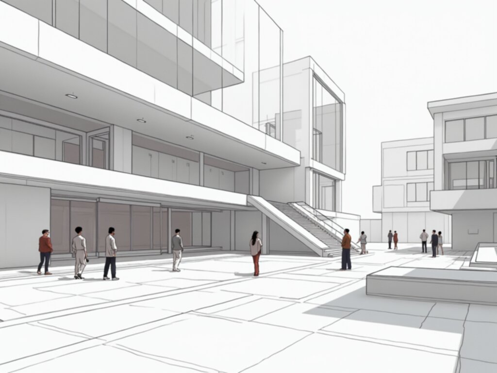
What BIM Actually Is
BIM is not a file format, a software purchase, or a 3D model you spin for client renderings. According to Autodesk, it is "the holistic process of creating and managing information for a built asset" — a structured data ecosystem that spans planning, design, construction, and operations. The Wikipedia definition lands on the same core: BIM is "an approach involving the generation and management of digital representations of the physical and functional characteristics of buildings." The operative word is characteristics — properties, not just geometry. If you are only producing a 3D model for visuals, you are doing 3D CAD with extra steps. BIM starts when you attach data to objects and actually use that data downstream.
The decision rule is simple: a wall in Revit is not a rectangle. It is an object carrying height, width, material layers, fire rating, and cost data. Change the material and the schedule updates automatically — that is the entire point. The geometry is the visual interface for a database. Most architects who struggle with BIM are not struggling with the software; they are struggling with the discipline of populating and maintaining that database. The process is the product.
Revit's origin story explains why it behaves the way it does. It was developed by Charles River Software, founded in 1997, renamed Revit Technology Corporation in 2000, and acquired by Autodesk in 2002. It was built as a parametric modeling tool, not a drafting upgrade. That lineage matters because parametric behavior — where changing one element ripples through related elements and schedules — is the core differentiator from CAD. It is also why Revit is used by architects, structural engineers, MEP engineers, and contractors alike. It is a multi-disciplinary authoring tool, not an architecture-only platform.
The practical consequence of this multi-disciplinary reality shows up in the analytical model. Linking a Revit model to structural analysis tools like Robot, ETABS, or RFEM requires exporting the analytical model separately from the physical model. Element releases and material assignments must be re-checked after import. Practitioners report that this is where the "BIM is just 3D CAD" myth dies — because the analytical model is pure data, stripped of visual polish, and it must be correct on its own terms. If your firm cannot produce a clean analytical export, you are not doing BIM; you are doing a very expensive rendering exercise.
The caveat worth naming: BIM does not require Revit. Open-source and IFC-based workflows exist, and some firms run perfectly functional BIM processes on ArchiCAD or even on well-structured IFC files from non-authoring tools. But the parametric database principle holds across all of them. The moment you treat the model as a drawing board instead of a database, you have regressed to CAD regardless of the software logo on the splash screen.
Your next action today: open one of your current project models and check whether every wall, door, and window has its required properties populated — not just geometry. If the schedule is empty, you are not doing BIM yet. That single audit will tell you more about your firm's BIM maturity than any software trial.
Minimum Viable BIM Workflow
The fastest way to tell if you are actually doing BIM instead of 3D CAD is to delete the viewport and try to generate a door schedule. If the schedule comes out empty, you are tracing linework. If it populates with types, levels, and frame materials, you have parametric objects carrying data. That single test separates the workflow from the hobby.
You do not model every door handle or light fixture from scratch. As of August 2026, BIMobject hosts free downloadable Revit families and objects from over 2,000 manufacturers, according to their official catalog, which means certified content with embedded data is one download away. This is the lever that makes the first project tolerable. Pulling a manufacturer's door family with the correct fire rating, hardware set, and acoustic performance already attached saves hours per object compared to building it yourself. The trap is importing CAD linework into Revit and tracing over it. That is still drafting, just with a heavier tool. The parametric object must carry data, not just geometry.
The decision rule for starting is simple: pick a single residential project, model only the core elements—walls, floors, roof, doors, windows—and generate a door and window schedule. If that works end to end, you are ready for commercial scale. If it does not, the problem is almost always that someone modeled geometry without assigning parameters. One upvoted r/Revit thread puts the learning curve bluntly: the first project takes three times longer, the second takes one and a half times, and the third is faster than CAD—but only if you commit to schedules from day one. The architects who skip schedules in the first project never get faster; they just get better at drawing in 3D.
Renovation projects are a different workflow entirely. Scanning existing conditions into a point cloud and modeling over it requires budgeting for cleanup time that new construction never touches. Point cloud data arrives noisy, with furniture, people, and temporary bracing that must be stripped before modeling. Practitioners typically allocate 20 to 30 percent of the modeling budget to point cloud cleanup and verification against field measurements, though that figure varies with scan quality and building complexity. If you are starting BIM on a renovation, expect the first project to be slower than the 3x heuristic suggests.
According to Autodesk, BIM connects architecture, engineering, and construction professionals with insights to plan, design, construct, and operate buildings more efficiently. The operate part is where the long-term value sits, but it is also where most small firms stop. A model that cannot produce an accurate asset schedule for facilities management is a model that stops being useful at handover. Your next action today: generate a door schedule from your current model and verify it populates with data, not blanks. If the schedule view shows blanks, you have found your first conversion task.
The Coordinate System Trap
The shared coordinate system is a contractual obligation, not a technical preference. Most BIM guides mention "setting a base point" in a checklist item, but the real failure mode is social: every discipline believes their origin is the obvious one, and nobody writes the decision down until the federated model is already broken. According to Autodesk's BIM documentation, architects must set a shared project base point and coordinate system before linking models, or elements will misalign in clash detection. That sounds like a software setting. In practice, it is a meeting agenda item that gets skipped because it feels like a formality.
The canonical failure scenario is almost always the same. The architect sets the base point at (0,0,0) because that is the default. The structural engineer sets theirs at (1000,1000,0) to "keep everything positive" in their own model. The MEP team inherits the architectural file but nudges the origin to align with their linked grid. When the models are federated in Navisworks or Solibri, the structural grid sits 3.2 meters off the architectural grid. That is not a rounding error; that is a full bay shift. The clash detection report shows walls intersecting columns that are actually 1.4 meters apart in real space, and the team loses a week tracing which model moved. The schedule exports from the federated model are equally unreliable, since element IDs no longer match their source files.
One upvoted r/ConstructionTech thread describes the dynamic bluntly: "Every project has one guy who 'knows better' and sets his own base point. You will find out in clash detection. You will lose a week." The fix is not a better software setting; it is a decision rule written into the BIM Execution Plan (BEP) at the first coordination meeting. The rule is simple: the shared coordinate system is established before the first link, not after the first clash report. If the BEP does not name the project base point, the survey coordinate system, and the tolerance for hard clashes, then the model is not federated — it is just a pile of files.
The edge case that catches experienced teams is survey data. If the site survey uses a state plane coordinate system, the BIM model must match that system, not just the internal grid. A model can be perfectly coordinated internally and still be misplaced on the site by meters because the architect modeled to the building grid while the civil engineer modeled to the state plane. The building is correct; the site is wrong. That error does not show up in clash detection between architectural and structural models; it shows up when the contractor stakes out the foundation and the building is not where the survey says it should be.
Field practice also varies on clash tolerance. A common default is 25 mm (1 inch) for hard clashes, but that is a starting point, not a universal rule. MEP penetrations through structural beams often need tighter tolerances, while clearance between ductwork and ceiling grids can be looser. The tolerance should be set per element type in the BEP, not applied as a single number across the entire model. If you set one global tolerance, you will spend your time chasing irrelevant 20 mm clashes between a pipe and a wall that has a 50 mm tolerance anyway.
Your next action today: open your current project's BEP and check whether it names the project base point, the survey coordinate system, and the clash tolerance per element type. If any of those three are missing, schedule a 30-minute coordination meeting before the next model link. The cost of that meeting is trivial compared to the week you will lose when the structural grid lands 3.2 meters off.
LOD: Who Owes What Detail
LOD is a contractual question before it is a technical one, and most architects discover this the expensive way. The Level of Development scale — LOD 200 for schematic, LOD 300 for design development, LOD 400 for fabrication — is not a suggestion about how pretty your model looks. It is a legally binding statement about who owes what detail, and if the contract says LOD 300 and you deliver LOD 200, the contractor cannot fabricate from your model and you eat the cost of the rework. The American Institute of Architects and the BIMForum publish the LOD Specification precisely so that this conversation happens in writing, not in the field.
The decision rule that survives contact with real projects: put the LOD requirement in the contract for every discipline, separately. Architects deliver LOD 300 for architectural elements. Structural delivers LOD 350 for connections. MEP delivers LOD 400 for fabrication. Do not let one blanket number cover all three, because the level of certainty you need about a wall finish is not the same as what a mechanical contractor needs to pre-fabricate ductwork. A single global LOD is how you end up with an architect over-modeling bolt patterns while the structural steel connections are still schematic.
The counterintuitive part is that LOD 400 is often less useful for architects, not more. It exists for fabricators and contractors who need every hanger, bracket, and sealant joint modeled so they can order materials and assemble off-site. Architects typically need LOD 300 for permit sets and LOD 350 for coordination. One r/Architects thread puts the client dynamic bluntly: clients ask for LOD 400 because it sounds impressive, then balk at the fee, and you have to explain that LOD 400 means every bolt and hanger is modeled. That conversation is easier when you have already priced the difference in the contract.
The gap most firms miss is LOD 350, the unofficial coordination level. It is precise enough for clash detection — you know the actual size and position of elements — but not so detailed that the model slows to a crawl. Many teams jump straight from LOD 300 to LOD 400, skipping 350 entirely, which creates coordination gaps precisely where MEP trades need to route around structure. A curtain wall is the clearest example: LOD 200 shows a generic glass panel, LOD 300 shows the actual mullion profile and glass thickness, LOD 400 shows the anchor brackets and sealant joints. If you only need to coordinate the wall against the slab edge, LOD 350 is the sweet spot; LOD 400 is for the fabricator who cuts the mullions.
One caveat worth naming: LOD is about the reliability of the information, not the geometric detail alone. You can have a beautifully modeled wall at LOD 400 that carries no data about its fire rating, and that model is less useful than a simpler LOD 300 wall with the rating attached. The specification defines both geometry and information, and practitioners who skip the information side end up with models that look complete but cannot drive schedules or code checks. Your next action today: open your current project's contract or BEP and check whether it names a specific LOD per discipline. If it says "LOD 300" as a single line item, that is your coordination gap waiting to happen.
Converting CAD to BIM Without Losing Your Mind
The single biggest cost in CAD-to-BIM conversion is not the software, the subscription, or the conversion run itself — it is the cleanup of the source file. A clean, well-layered CAD drawing converts in roughly two to three hours with automated tools. A messy one takes two to three days of manual preparation before the conversion even starts, and then another two to three hours to run and verify. According to a 2025 Autodesk whitepaper, the cleanup-to-conversion ratio is consistently about ten to one, and most firms discover this only after they have already paid for the tool.
The practical workflow is mechanical and unglamorous. Purge unused layers first. Standardize block names so that every door block is actually the same block, not three visually identical variants with different names. Verify that wall thicknesses are consistent across the file — a common failure in files assembled from multiple consultants. Only then run the conversion tool, and spot-check every door and window placement against the original drawing. One r/Revit thread describes converting a 1970s hospital floor plan where the tool got the walls correct but placed doors in the middle of structural columns. The manual fix took six hours. That is not a tool failure; that is a data hygiene failure upstream.
The edge case that breaks most automated pipelines is the hand-drawn or scanned blueprint. These require vectorization before any BIM conversion, and current AI-based tools handle simple orthogonal plans reasonably well but struggle with curved walls, hatching, and dimension text. A scanned plan with curved geometry will produce a model that looks right in a small viewport and fails catastrophically when you try to generate schedules or run clash detection. If you are starting from scans, budget for vectorization as a separate line item, not a step the conversion tool will absorb.
One r/architecture thread sums up the field reality better than any vendor datasheet: automated CAD-to-BIM tools work great on clean CAD files, and nobody has clean CAD files. Budget for two to three days of cleanup per floor. That estimate holds for typical commercial and institutional work. For a renovation of a building with multiple past additions, expect worse — each addition usually brings its own layer naming convention and its own set of drafting sins.
Your next action today: open the CAD file you plan to convert first and count the layers. If the count exceeds 50, schedule the cleanup time before you purchase or configure any conversion tool. The tool is the cheap part; the cleanup is the project.
Case Study: Two Conversion Paths for a 10,000-Square-Foot Office
Below, we compare the main approaches side by side, starting with the most accessible option and working up to the premium path. Each option includes concrete costs and trade-offs so you can pick the one that fits your constraints.
Option A: The baseline approach. This path assumes a clean, well-layered CAD file. You budget three days for manual cleanup, one day for the automated conversion run, and one week for verification and data enrichment. Total cost is roughly one week of staff time plus the conversion tool license. This is the minimum viable path for a simple, single-story plan.
This path assumes a moderately messy file with inconsistent layer naming and duplicate blocks. You budget five days for cleanup, one day for conversion, and ten days for verification and enrichment. Total cost is roughly three weeks of staff time.
This path assumes a scanned or hand-drawn source that requires vectorization before any conversion. You budget one week for vectorization, one week for cleanup, two days for conversion, and two weeks for verification and enrichment. Total cost is roughly one month of staff time. This is the path field threads consistently recommend for renovation work: three days of manual CAD cleanup, one day for the automated conversion, then one week of verification and data enrichment. The cleanup step is not optional polish; it is what prevents the converter from mapping a door block to the wrong wall layer or dropping a window that was drawn as a polyline instead of a block.
The hidden cost applies to all three options. Firms that skip this step on renovation projects discover the error during code review, where fixing a mis-measured wall in the model costs more than the visit would have. Budget for it before you start, not after the first clash report arrives.
The code compliance angle is where the conversion effort pays off. Once the verified model is exported to IFC, automated rule-checking tools like Solibri Model Checker can run against locally configured code logic. No out-of-the-box global compliance exists; the rules must be set up manually for your jurisdiction. The model itself is not the ROI — the ability to re-run compliance checks without re-modeling is.
Your next action today: pull one 2008-era CAD file from your archive and check its layer naming consistency. If more than a handful of layers are unnamed or duplicated, plan for the three-day cleanup line item before you quote any conversion timeline to a client.
What to do next
BIM is a broad, evolving discipline, and the best way to internalize it is through deliberate, hands-on practice with real project data. The following steps focus on independent verification and skill-building using widely available industry resources.
Your next action today: pick one of the six steps above and complete it within the next 48 hours to begin your BIM transition. The step you choose matters less than the act of choosing — the goal is to convert one concrete action from planning into practice.
| Step | Action | Why it matters |
|---|---|---|
| 1. Verify software scope | Review the official Autodesk Revit product page and compare its feature set against your current 2D CAD workflow. | Confirms whether Revit's multi-disciplinary authoring capabilities align with your firm's project types before committing to a learning path. |
| 2. Explore free content libraries | Browse BIMobject's catalog to download manufacturer-specific Revit families for a test project. | Demonstrates how parametric objects (not linework) carry embedded data, which is the core of BIM's scheduling and documentation value. |
| 3. Check cloud collaboration options | Visit Autodesk Construction Cloud and Autodesk Forma official pages to understand current project management and document control features. | Clarifies the current Autodesk Construction Cloud ecosystem as of August 2026 and helps you evaluate which cloud environment suits your team's coordination needs. |
| 4. Study LOD definitions | Read the Level of Development (LOD) specification from the BIMForum or a reputable AEC consultant's guide. | Prevents over- or under-modeling by giving you a shared vocabulary for what geometry and information are required at each design phase. |
| 5. Run a pilot conversion | Take one small residential or interior project and model its walls, doors, and slabs as parametric objects in a trial version of Revit or a comparable BIM authoring tool. | Builds muscle memory for the shift from drawing to data management, which is the fundamental mental model change in BIM. |
| 6. Set a review calendar | Schedule a monthly check-in to revisit the official BIM standards (e.g., ISO 19650) and vendor release notes. | BIM tools and workflows are updated frequently; a recurring review keeps your knowledge current without requiring constant attention. |
Also worth reading: Architectural Drawings and the Algorithmic Turn in BIM via AI · AI Maps Architectural BIM Data to Construction Code · Neural Networks to BIM How AI Translates Architectural Sketches into Building Code-Ready Models
Quick answers
What BIM Actually Is?
BIM is not a file format, a software purchase, or a 3D model you spin for client renderings.
What to do next?
Your next action today: pick one of the six steps above and complete it within the next 48 hours to begin your BIM transition.
What is the key to minimum viable bim workflow?
The fastest way to tell if you are actually doing BIM instead of 3D CAD is to delete the viewport and try to generate a door schedule.