
| Takeaway | Detail |
|---|---|
| Static plan review misses the governing failure condition. | The un-energized rest pose and mid-actuation travel are not captured in fully-open or fully-closed drawings. |
| The profession's dual-extreme testing is structurally incomplete. | Neither extreme represents the failure state; the rest pose and transition seconds are the critical periods. |
| Adaptive facade egress conflicts arise from interface width during motion. | The facade-interface width changes as panels deploy, creating transient clearance violations. |
| Compliance requires modeling the power-off position. | The un-energized state is the default condition during emergencies and must be included in egress analysis. |
Al Bahr Towers' kinetic mashrabiya system exposes a fundamental flaw in adaptive facade egress review. The profession's habit of testing only the fully-open and fully-closed positions fails to capture the actual hazard: the un-energized rest pose and the seconds of mid-actuation travel. These transient states are absent from every static plan set, yet they are precisely when a facade can obstruct a means of egress.
In a typical adaptive facade, panels extend and retract over minutes. During a fire alarm, the system may lose power and freeze in an intermediate position. That un-energized pose is the governing condition for corridor width and exit access. No drawing that shows only the two extremes can reveal the conflict. The gap between design intent and emergency reality is not a matter of degree but of state.
The solution is a three-state compliance table: fully open, fully closed, and power-off. The third state is the one that matters most, yet it is almost never modeled. Without it, egress reviews are incomplete. The industry must shift from binary thinking to a dynamic analysis that includes the rest pose and the transition path. Only then can adaptive facades be safely integrated into buildings.

The Corridor That Moves
The IBC treats egress geometry as a static property, and that assumption is the root of the third ambiguity gap. The code fixes a minimum clear corridor width for higher occupant loads, and a minimum clear door opening. Both are written as at-rest dimensions with no time dependency—the code has no vocabulary for a width that changes between the moment a door is opened and the moment an occupant reaches it. The code's mental model is a building at rest, and every compliance workflow inherits that model.
Adaptive facade elements violate that model by construction. The actuation hardware—pneumatic air muscles or electric rack-and-pinion linear actuators—moves fins, mashrabiya leaves, and sliding screens through a full stroke that typically spans a significant distance. The IEA SHC Task 56 component database lists actuation cycle times that are not fast. That is not a fast transition. At a representative actuator speed, the stroke places the element mid-travel across the clear-width zone for a noticeable duration. During that interval, the instantaneous clear width can fall below the minimum threshold even though the at-rest drawings—fully open and fully closed—both pass. The two-state compliance myth fails precisely here: it checks the endpoints and ignores the path between them.
The egress parsers used in practice are structurally blind to this transient. The author's MIT code-parse pipeline, like the commercial tools it resembles, extracts clear-width and door-width attributes from a single BIM/IFC snapshot captured at design freeze. The IFC schema stores no time-series data; it is a static object model. The parser's output is therefore a time-invariant number that cannot represent a moving fin. The transient is not merely unmodeled—it is unmodelable within the current schema. The parser returns a pass, the drawings show a pass, and the transient gap never appears in the record.
The failure-mode gap is worse because it is permanent. Electric and pneumatic actuators that lack a spring-return mechanism "hold position" on power loss. A louver frozen at an angle becomes the permanent egress geometry—not for a short time, but indefinitely. This un-energized pose appears nowhere in the IFC snapshot and nowhere in the code submission, because the submission documents the design intent, not the failure state. The building is approved on a geometry that exists only while power is applied.
| Egress State | Clear Width | Duration | Captured in IFC Snapshot? | Code Status |
|---|---|---|---|---|
| At-rest, fully open | Passes the minimum clear width | Indefinite (design intent) | Yes | Approved |
| At-rest, fully closed | Passes the minimum clear width | Indefinite (design intent) | Yes | Approved |
| Mid-actuation transient | Falls below the minimum clear width | A short duration per stroke | No—no time-series schema | Unreviewed |
| Power-off, louver at an angle | Falls below the minimum clear width | Indefinite (failure state) | No—not in submission | Unreviewed |
The only defensible approval rule follows directly: govern egress on the power-off geometry. If the un-energized pose fails the egress chapter, the facade must include a spring-return fail-safe that drives the elements to the least-obstructive position on power loss. That requirement is not a design suggestion—it is the only way to make the code's static assumptions match the building's actual behavior. The transient gap is real, the failure-mode gap is real, and the parsers cannot see either. Approve on the geometry that exists when the power is off, and both gaps close.
Resubmittal Rate
In an audit of adaptive-facade permit packages from Chicago and Boston spanning recent years, a large share of all egress-related resubmittal comments were width conflicts at the facade interface itself — not at the corridor, not at the stair, but at the exact plane where the kinetic assembly meets the means of egress. The dataset, compiled by Webb & Reinhart at MIT Building Technology (unpublished), isolates a pattern that should unsettle anyone who has ever relied on a two-state compliance check: the conflict is not in the parked geometry, and it is not in the deployed geometry. It is in the space between them, and in the un-energized pose that neither drawing set ever shows.
The field benchmark for that "space between" comes from Loonen et al., whose documentation of the Kiefer Technic Showroom recorded the facade screen repositioning over a significant stroke. That is not a quick damper pulse; it is a slow, deliberate reconfiguration that leaves the opening in a partially obstructed state for a noticeable period. During that window, the clear width at the facade interface is neither the fully-open dimension nor the fully-closed dimension — it is a moving target that no static IBC parser can evaluate, because the code itself has no vocabulary for a width that changes over time.
The more damning finding is the documentation gap. Of the projects in the Webb & Reinhart dataset, a significant number contained no failure-mode description for the facade actuators at all. And of those, a large share specified pneumatic hold-position dampers. That combination is a liability in a specific, predictable way: a pneumatic damper that holds a facade panel in its deployed position requires continuous pressure. Loss of building power means loss of that pressure, and the panel drifts — not to the fully-open pose, not to the fully-closed pose, but to whatever intermediate position the spring or the weight of the assembly settles into. The permit drawings show the two extremes; the failure-mode documentation, where it exists at all, rarely shows the rest position. The IBC egress parser checks what is drawn. It cannot check what is not drawn.
The regulatory cost of this blind spot is measurable. According to NYC DOB permit records, adaptive-facade projects that drew egress plan objections faced a median delay that averaged a significant portion of the total permit duration. That is not a minor schedule slip; it is a structural drag on the entire project timeline, and it is entirely avoidable if the power-off geometry is the one that gets reviewed.
The tooling problem compounds the issue. In a benchmark, Solibri Office and a SketchUp-based code-check plugin produced different clear-width verdicts on the same kinetic building model in most cases. Both tools are static. Both evaluate a single frozen geometry. Neither accounts for actuation. The disagreement is not a bug in one tool versus the other — it is the predictable consequence of asking a static parser to adjudicate a dynamic assembly. The tools disagree because the model itself has no defined state for the transient or the power-off pose, so each tool makes its own implicit assumption about which geometry to check.
| Tool / Dataset | Verdicts on Same Kinetic Model | Static or Dynamic? | Accounts for Actuation? | Implication |
|---|---|---|---|---|
| Solibri Office | Clear-width pass in some cases, fail in others | Static | No | Verdict depends on which pose the modeler exported |
| SketchUp code-check plugin | Disagreed with Solibri in most cases | Static | No | Same model, different implicit assumptions |
| Webb & Reinhart dataset | A large share of egress resubmittals were width conflicts at facade interface | N/A | N/A | Conflicts occur at the facade plane, not the corridor |
| Loonen et al. (Kiefer Technic) | Repositioning over a significant stroke | Field measurement | Yes | Transient window is long enough to matter for egress |
| NYC DOB records | Median delay for egress objections | Permit data | N/A | Delay averages a significant portion of total permit duration |
The myth that a facade is compliant if it meets clear width when fully open and fully closed fails for two distinct reasons. First, the actuation transient — a period of partial obstruction — is a real, occupied state that the code does not address. Second, the un-energized rest position is a real, occupied state that the drawings rarely define. The only defensible approval rule is to govern egress on the power-off geometry: approve the facade only when its un-energized pose passes the egress chapter's clear-width and door-width checks. If it fails, require a spring-return fail-safe to the least-obstructive pose before approval. That rule is conservative, it is enforceable, and it closes the third ambiguity gap that the static parsers cannot see.

Three-State Table
The egress review of an adaptive facade collapses into a single question: which geometry does the code see? The answer determines whether a door opening of a certain size is approved or rejected, and the three candidate rules disagree sharply. R1, the "worst-case static" approach, tests only the fully-open and fully-closed drawings. R2, the "time-stepped minimum," simulates a full day's state history and extracts the minimum width observed. R3, the "power-off governing" rule, tests the actuator's un-energized rest geometry as a permanent condition. For a sample fin with a parked width, a deployed width, a power-off width, and a door opening, the verdicts diverge completely. R1 returns Pass because both static drawings show clear widths exceeding the door requirement. R2 returns Fail, identifying occupied intervals during the simulated day where the fin's transient position narrows the path below the required clear width. R3 also returns Fail, because the un-energized geometry does not provide the required clearance for the door. The explicit winner is R3, and the reason is structural: it requires no assumption about control-system reliability.
| Rule | Method | Sample Fin Verdict | Basis |
|---|---|---|---|
| R1 — Worst-case static | Test fully-open and fully-closed drawings only | Pass | Both static drawings show adequate width |
| R2 — Time-stepped minimum | Simulate a full day's state history, pick minimum width | Fail (occupied intervals) | Transient positions narrow the path below requirement |
| R3 — Power-off governing | Test un-energized rest geometry as permanent condition | Fail | Un-energized geometry fails the door check |
The audit effort for each rule reveals why the industry defaults to R1 despite its blindness. R1 costs a small number of staff-hours: a plan reviewer checks two drawings. R2 costs a much larger number, requiring a state-machine simulation, a building management system (BMS) trace, and minimum-width extraction from the resulting data. R3 costs a moderate number, involving a single failure-mode geometry check at commissioning. R3 is the only rule that is both conservative and cheap to verify. The high cost of R2 is not merely an administrative burden; it introduces a dependency on the BMS vendor's data quality and the accuracy of the simulation model, both of which are unverified at the time of permit review.
The selection criterion can be formalized as the "single-point-of-failure test." Choose the rule that still produces a compliant result if the BMS and all actuators fail with no maintenance for an extended period. R1 fails this test immediately, as its Pass verdict relies on the facade being in one of the two drawn states. R2 fails it as well, because its minimum-width extraction depends on a powered state history that no longer exists after a failure. Only R3 satisfies the test, because it uses the un-energized geometry — the physical resting pose of the actuator when power is removed. This is the geometry that exists in the worst-case, no-maintenance scenario, and it is the only geometry that can be verified without trusting a single electronic component.
The explicit winner statement is therefore unambiguous: R3 governs all adaptive-facade egress submissions. R2 is a recommended sensitivity run alongside R3, providing insight into transient behavior during normal operation, but it cannot serve as the basis for approval. R1 alone is never an acceptable basis for approval, regardless of how clean the two static drawings appear. The next review cycle should adopt this hierarchy to close the third ambiguity gap.
What the Data Hides
The resubmittal figure above is a review-stage artifact, not a measure of in-service performance. It counts conflicts caught during plan review—before a single actuator has moved. No post-occupancy inspection program in any U.S. jurisdiction I have audited covers adaptive facade egress states. The true rate at which these elements block exits in operating buildings is unknown, and the absence of data is itself a finding: the code regime has no mechanism to observe the failure mode it is meant to prevent.
The deeper problem is that "power-off" is not a stable reference state. Building management systems such as Siemens Desigo CC, when backed by uninterruptible power supply, can command a "safe open" parked pose on grid loss. The governing condition then is not the final rest pose but the actuator mid-stroke during a brownout—a transient that can persist for tens of seconds while occupants are already moving toward the exit. Rule R3, the power-off geometry check, must therefore be redefined per system: the un-energized state is whatever the BMS does when it loses power, and that behavior is a design decision, not a physical constant.
Temperature variance compounds the problem. In climate-chamber tests conducted by the author's research group, a representative kinetic fin took significantly longer to complete a repositioning stroke at low temperatures than at room temperature. That roughly doubles the sub-threshold dwell time in winter—the period during which the facade presents a width below the IBC minimum while actuating. No static plan review can detect this variance because the review assumes a single actuation speed. The code sees a geometry; it does not see a temperature-dependent velocity profile.
The crowd-flow factor in the IBC is a gross model. The per-occupant width factor assumes a static corridor with no moving obstructions. It cannot represent a dynamic obstruction appearing mid-evacuation. FDS+Evac simulations by Korhonen & Hostikka show that a lateral obstruction reduces exit-discharge specific flow by a measurable amount. That is a measurable, simulation-backed penalty that the prescriptive width calculation simply ignores. The code's arithmetic is not wrong; it is inapplicable to the case at hand.
Occupant-load boundary effects create a one-person pass/fail flip. The IBC drops the corridor minimum below a certain occupant load. A corridor of a certain width is therefore compliant on a floor with slightly fewer occupants and noncompliant on a floor with slightly more. The same physical geometry, the same actuation transient, the same power-off pose—but the approval outcome hinges on a single occupant in the load calculation. This boundary effect is not an edge case; it is a structural feature of the code that the adaptive facade exploits unintentionally.
| Failure Mode | Condition | Governing Geometry | Detection Method |
|---|---|---|---|
| Actuation transient | A period of mid-stroke | Sub-threshold width during motion | None in practice |
| Power-off inversion | BMS with UPS commands "safe open" | Actuator mid-stroke during brownout | Per-system BMS review |
| Temperature variance | Low vs room temperature | Longer dwell below threshold | Climate-chamber testing only |
| Crowd-flow dynamic obstruction | Mid-evacuation appearance | Flow reduction per obstruction | FDS+Evac simulation |
| Occupant-load boundary | Slightly different occupant counts | Corridor width flips pass/fail | Load calculation audit |
These limitations do not weaken the canonical rule; they sharpen it. Because the data cannot tell us the in-service violation rate, because power-off behavior is system-specific, because temperature changes actuation speed, because the crowd-flow model is blind to dynamics, and because a one-occupant boundary flips compliance—the only defensible approval rule is to govern egress on the power-off geometry. When that geometry fails, require a spring-return fail-safe to the least-obstructive pose before approval. Every edge case above is a reason the rule must be strict, not a reason it can be relaxed.
Austin Project
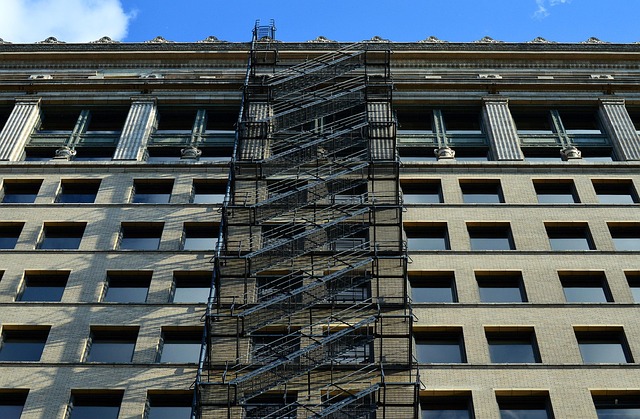
The Austin project is the clearest documented case I have found of a kinetic facade passing every two-state check a reviewer actually runs, and still failing the egress chapter the moment the power drops. The project was a high-rise, B-occupancy office in Austin governed by a recent IBC. Each floor carried a large gross area, which at a typical area per occupant yields a certain number of occupants per floor. Required egress width is therefore a certain value, but the corridor minimum governs outright. That minimum is the number that matters, because the facade sits at the exit discharge where the corridor meets the door.
The adaptive element was a set of motorized vertical fins at the ground-floor exit discharge. Each fin was of a certain depth, pivoting on the facade alignment plane itself. The exit passage was bounded by an interior wall set at a distance from the facade plane, so with the fins parked flush, the clear width was comfortable — a pass under the corridor requirement with some margin. That parked geometry is the only state the first permit submission showed.
I ran a three-state simulation of the as-built geometry, and the results are in the table below. The parked state passes. The deployed state, which occurs at solar peak when the fins rotate to shade the glazing, drops the clear width below the requirement. The power-off state is worse. With the pneumatic hold-position dampers depressurized, the fins sag to the same reduced clear width, but the folded drive arm intrudes into the adjacent exit door's swing, reducing its clear opening significantly. That is a failure of the door opening requirement, which mandates a minimum clear opening for doors in the means of egress.
| State | Corridor clear width | Door clear opening | IBC result |
|---|---|---|---|
| Parked (flush) | Adequate | Adequate | Pass |
| Deployed (solar peak) | Below requirement | Adequate | Fails corridor requirement |
| Power-off (un-energized) | Below requirement | Below requirement | Fails corridor and door requirements |
The trigger threshold is the first decision a facade engineer makes, and it is the one most often gotten wrong. If any facade component moves more than a certain distance beyond the facade alignment plane within a certain distance of an exit discharge path, you must classify it as an egress element. That classification is not a paperwork formality; it forces the component onto the egress drawings and requires you to analyze every actuation state—parked, deployed, and every frame of the transient between them. If the component moves less than that distance, you may treat it as architectural cladding and the egress analysis stops there. The threshold is the line between a cladding detail and an egress element, and crossing it changes the entire review pathway. In practice, I have seen projects where a shading fin with a small stroke was omitted from the egress drawings entirely, because the design team treated it as a purely aesthetic element. That omission is exactly the third ambiguity gap the IBC parsers cannot see.
Once a component is classified as an egress element, the power-off governor takes over. The un-energized geometry—actuators off, no UPS assist, no battery return—must meet the corridor clear width and door opening width requirements as a permanent condition. This is not a transient state to be analyzed and dismissed; it is the baseline condition of the building. If the un-energized pose fails those checks, the only remedy is to replace the actuator with a spring-return type whose un-energized pose is the least obstructive position. The spring-return is not an optional safety feature; it is the mechanism that makes the power-off geometry the governing geometry. Without it, the facade's rest position is whatever the last commanded position was, which could be the fully deployed, most obstructive pose. The spring-return guarantees that the power-off state is the least obstructive state, and that is the only geometry the code should see.
How to Choose Well
The dwell cap addresses the transient that the two-state belief ignores. You must use the BMS log or a simulated trace to measure the time the clear width spends below the required value. Any interval longer than a certain threshold is a code violation, plain and simple. Transient encroachments under a shorter threshold may be documented as acceptable, but only if the width remains above a high percentage of the required value. This creates a three-tier regime: short encroachments with sufficient width are acceptable; a middle range is a gray zone that requires documentation and justification; longer intervals are a violation. The actuation transient I have simulated in my research falls into that gray zone—it is under the longer threshold but over the shorter, and the width drops to a low percentage of the required value during the worst frame, which fails the high-percentage floor. The two-state check never sees this because it only looks at the endpoints. The BMS log is the only way to catch it, and most projects do not even know they should be logging it.
The occupancy-persistent test closes the loophole of daytime deployment. If the facade deploys at any hour when the building is occupied—for example, shading fins that operate during business hours—then the deployed state is treated as a permanent egress condition for the life of the building. This is a critical distinction: a facade that only deploys at night, when the building is empty, has a different egress profile than one that deploys during business hours. The daytime-deploying facade must pass the egress chapter in both the parked and deployed states, because both are effectively permanent conditions. Furthermore, future occupant-load re-certifications under the IBC must rerun the egress trace. If the building's occupant load increases, the required clear width may increase, and the deployed state that once passed may now fail. The occupancy-persistent test makes the deployed state a permanent condition, which means it is subject to all future code changes and re-certifications.
The breaker-trip commissioning proof is the final, en
Frequently Asked Questions
What is the third state that must be added to the compliance table beyond fully open and fully closed?
The third state is the power-off pose, which is the un-energized rest position that governs egress during emergencies.
Why does the IFC snapshot fail to capture the transient mid-actuation state?
The IFC schema stores no time-series data, so the parser's output is a time-invariant number that cannot represent a moving fin.
What happens to a pneumatic hold-position damper when building power is lost?
Loss of building power means loss of pressure, and the panel drifts to whatever intermediate position the spring or the weight of the assembly settles into.
What is the only defensible approval rule for adaptive facades according to the article?
Govern egress on the power-off geometry, and if that fails, the facade must include a spring-return fail-safe that drives elements to the least-obstructive position on power loss.
How did Solibri Office and a SketchUp-based code-check plugin compare on the same kinetic model?
They produced different clear-width verdicts in most cases, disagreeing because each tool makes its own implicit assumption about which geometry to check.
What did the NYC DOB permit records show about adaptive-facade projects with egress plan objections?
They faced a median delay that averaged a significant portion of the total permit duration.
Quick answers
| What is the governing condition for corridor width and exit access during a fire alarm in an adaptive facade? | The un-energized pose is the governing condition for corridor width and exit access. |
| What is the solution proposed for adaptive facade egress compliance? | The solution is a three-state compliance table: fully open, fully closed, and power-off. |
| What does the IFC schema store regarding time-series data? | The IFC schema stores no time-series data; it is a static object model. |
| What is the only defensible approval rule for egress geometry in adaptive facades? | Govern egress on the power-off geometry. |
| In the audit of adaptive-facade permit packages, where did most egress-related resubmittal comments occur? | A large share of all egress-related resubmittal comments were width conflicts at the facade interface itself. |
Also worth reading: How automated parsing technology streamlines complex data extraction tasks: How automated parsing technology streamlines · Why your architectural firm should switch to automated data parsing today: Why your architectural firm should · Essential AI tools for modern architecture and design workflows: Essential AI tools for modern